
Surveying Boats With
Molded Integral Grid Systems
by David H. Pascoe, Marine Surveyor
Fiberglass boats built with internal liners have been around for a long time. Typically, a liner is a premolded internal component, the purpose of which is to provide the basis for the interior layout. Over time, this function has evolved and has slowly taken over the function of providing internal hull structural support as well.
Contents
Grid/liner
Hence the liner has evolved to the term "grid/liner" where the function of the liner is included to take over the role of conventional framing systems such as individually laid up glass-on-wood stringers. Surveyors know that working with liners can cause problems, not only with access for inspection of the internal hull - often they make large parts of the hull inaccessible - but because of the difficulties imposed by the design for bonding the liner to the hull. If the surveyor can't reach the areas, neither can the builder, and so the manner in which it is attached to the hull has to be suspect unless proven otherwise.
Wellcraft 34 Grand Sport
The Wellcraft 34 Grand Sport is a good example of a boat with a full liner forward that obscurred most of the internal hull framing. These boats also had major structural shortcomings that resulted in serious structural failures. In most cases, examination of what little could be seen of the internal hull would yield little evidence of the problem. However, with these boats the bending and twisting of the hull was so severe (they only had one bulkhead in them) that the interiors were shifting and breaking up. If you knew what you were looking for, it was relatively easy to detect the problem. Just inspect the interior for unusual gaps between components, broken joints, loose moldings, screws backing out and little piles of wood dust where parts were rubbing together. If one isn't aware of the problem, its quite easy to miss it because the effects may be quite subtle until the whole structure begins breaking apart.
Yet for most boats with liners there was usually some degree of access so that one could get at least a fair look at the structurals.
Now the growing use of grids is going to make inspection of the internal hull more difficult than ever. The reason is because grids are combining the function of liner and framing system all rolled into one. The grids are reducing visual access to the hull interior more than ever, often to as little as 10%. This is a departure from typical liners that generally do not take over the function of frames. Normally, the liner sits on top of frames.
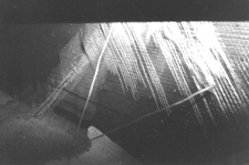
This sailboat uses a premolded grid that completely disbonded from the hull.
The problem here was inadequate tabbing which can be seen broken loose at left, center and right of photo. Only the webs are glassed while the longitudinal section (seen at top) is not bonded to the hull at all.
One-piece grids
If you thought lack of access gave you problems with liner boats, you'll be even more thrilled with what you see arriving in the near future. One-piece grids are being used to virtually eliminate the traditional framing system, replacing it with a liner system that is literally glued into the hull. Glued, you say? Well, they call it bonding putty but an adhesive by any other name is still a glue.
Those of you experienced with Hunter sail boats will know what I mean. They were one of the first to use full interior grids, albeit not necessarily a liner, and much of their product line suffered massive bonding failures, including their large 60 footer.
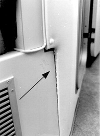
The framing system in this boat was reduced from a 4 stringer system to 2 stringers because it was thought that the liner would provide the needed extra strength.
The liner broke loose and the stringers started to fracture as shown in this photo. The area of the break was completely obscurred by the liner and was not discovered before the bottom cracked open.
What's wrong with grids?
So what's wrong with grids, you ask? The reason behind them is, of course, efficiency, making the boat easier and faster to build. And that is always the signal for the surveyor to open his eyes a little wider, for another interpretation could be "cutting corners.
Bonding
Start with the fact that grid/liners are basically glued into the hull.
Now, I don't know about you but I've never seen anything that was glued
together being as strong as a component that's all of one piece. That's
despite all the loud and fancy the advertising about adhesives. The only
things that glue together well are parts with identically uniform or
mirror profile surfaces. For example, gluing two pieces of wood together
that are perfectly flat makes for a very strong joint. But allow the
slightest surface irregularlity or out of squareness and the joint becomes
very weak. Unfortunately, the interiors of laminated hulls can hardly be
called uniform. Our experience with bonding putty in cored hulls tells us
that there's not likely to be any better level of success in this
application than for foam cores. See related article Hi Tech Materials.
Structural members
Next, let's consider the functions of the structural members that the grids are taking over. The function of the bulkhead is primarily to prevent a hull from wracking or twisting in a torsional mode. Additionally, it also serves as a transverse frame.
Stringers are longitudinal frames, probably better represented by the word girder than frames since we traditionally think of frames as transverse members. Stringers are uniquely critical to power boats since powerboats travel at much higher speeds. The forces that work on a power boat hull tend to want to break it in half, similar to the way a bridge wants to collapse in the middle. Thus, good, strong stringers are needed to keep the hull from bending in this direction. The above photo shows what happens when this principle is compromised.
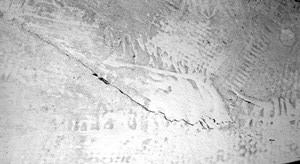
Bonding failures can sometimes be difficult to detect.
This broken liner bond was only discovered by sounding because the break was obscurred by a dirty bilge. In this photo, it is cleaned for purposes of clarity.
At a time when I taught a course on marine surveying, I used a shoe box to demonstrate the forces that work on a power boat hull. A small lead ingot was placed in the center of the box. Then I picked up the box and it buckled because it was too weak to carry the weight. Next, the lid was put on and taped in place. Taping the box lid in place represents the function of the deck; it is a horizontal bulkhead. When lifted, the box still buckled, although not quite so badly as when the lid is not taped in place because the secure lid adds strength. Just not enough.
Then I put two 1/4" square strips of wood on the bottom of the already buckled box and set the ingot on top of the strips. Without putting the lid on, I picked up the box. By now you get the picture that, even though the strips of wood weren't attached to the bottom of the box, they served to distribute the load of the ignot over the length of the bottom. When lifted, the buckled box did not buckle at all.
Now lets introduce grids into bottom of the hull and see what we've got. Not surprisingly, two different boats I've seen have grids that do not make any attempt at providing continuous stringers. One had stringers in the liner running half the length of the hull, while the other had a section four feet long where the stringers disappeared in the middle. Imagine taking a boat and cutting out four feet from all four stringers in the midships section! On this boat, the stringers were eliminated so that they could put in a very large fuel tank. The same thing was happening to this boat as our carboard box with the ingot.
Additionally, many of these grid systems are found to have the fault of creating dog legs in in longitudinal framing systems. I you don't understand the problem with this, just imagine a bridge span with a dog leg in it. A dog leg changes direction of the load suddenly, creating a local high stress point which may result in stress cracking and failure.
The problem here is that the design of the grind/liner may involve so many trade-offs that the designer ends up compromising the essential structural elements. In order to get components to fit, structural elements are sacrificed. In and of itself, this is a problem. But now let's add to the mix the fact that the whole grid system is glued into the hull. Combined with a compromised structural system, how well is it going to hold up?
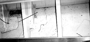
When full inner liners are used, internal plywood partitions are usually secured to the liner with screws. If the liner is loose and working, it is very likely to result in misalignment of internal components. In this case, the large gap and shifting of a partition was a dead giveaway of a structural problem. Further evidence was in the form of screws backing out of parts fastened together.
New surveying techniques
I'll let you be the judge. In the meantime, these new designs are going to require some new surveying techniques since what you previously were surveying visually will no longer be visible. Fortunately, there are some techniques that will partially overcome these limitations.
Because the use of grid/liners will essentially act as an inner and outer skin, somewhat similar to a cored hull, finding disbonded areas shouldn't be particulary difficult. If, because of the liner, builders cut down on hull laminate thickness, as I believe they will, then detecting disbonding will be even easier. If you thought hammering on the bottom of a hull was a primitive survey technique, wait until you hear what I'm about to suggest.
If a liner bonded to a hull comes unglued, in all probability a gap will open up. Sounding with a hammer is not going to detect this gap because the bonding putty is considerably less dense than glass laminate. The hammer may return a sudden change in sound, but then again, it's just as likely not to. The answer lies in using something quite a bit heavier than a hammer, such as a heavy chunk of wood like a piece of 2" x 4". Now give the hull a moderate hit with the wood.
If there's a gap between hull and liner, the two parts should hit together and return a sort of clacking sound - the two pieces hitting together. The sound will come across as sort of a double clack, first the wood hitting the hull, and then the hull and liner contacting. This techique is highly likely to find major areas of disbonding where the interior is not accessible.
Naturally, going over the whole bottom with a big hunk of wood will require the strength of a 24 year old linebacker. So to reduce the effort, we can go over all the internal areas that are accessible with the hammer. This is because the parts of the liner that are glued to the hull are going to be quite thin. The hammer should return the usual disbonded sound. Once you've done all of the interior that you can, then you target only the more limited areas externally for the big hit.
For a 30' boat , this may entail about 30 minutes more work, mainly because of the additional interior sounding that you would not otherwise be doing. it's well worth the extra effort because if you ignore this, as I've explained above, the risks of getting tagged for not discovering a major problem are unacceptably high.
- View gridded systems and large liners with great suspicion.
- Take every opportunity to sound out the internal bonding points
wherever accessible
- Examine the grid system for structural design faults such as
non-continuousstringers and dog legs. When such indicators are present,
be extra cautious.
- Examine the fit of the interior components for signs of working,
misalignment, loose screws or little piles of dust caused by abrasion of
working parts.
- Use these new but crude techniques to further prove out the grid
bonding.
- Remember that the grid is the framing system: if it's broken
loose from the hull, the effects are no different than top hat stringers
that are broken loose.
- Remember that the best liability insurance you can get you can
provide for free yourself by doing as good a job as possible.
- Take pictures: document your file with the good, the bad and the ugly. There's nothing like photographic evidence to prove your point.
First posted on 6/08/97 at David Pascoe's site www.yachtsurvey.com.
Page design changed for this site.
Professional Marine Surveys
- Hull Design Defects - Part I
- Hull Design Defects - Part II
- Surveying Boats With Molded Integral Grid Systems
- Surveying Wood Hulls
- Avoiding the Blister Blues
- Sinking of EL TORO II
- Storm Damaged Boats
- Insurance Surveys and Reports

Over 180
Online Articles by David Pascoe

Power Boat Books
 Mid Size Power Boats
 A Guide for Discriminating Buyers
Focuses exclusively cruiser class generally 30-55 feet
With discussions on the pros and cons of each type: Expresses, trawlers, motor yachts, multi purpose types, sportfishermen and sedan cruisers.
Selecting and Evaluating New and Used Boats
Dedicated for offshore outboard boats
A hard and realistic look at the marine market place and delves into issues of boat quality and durability that most other marine writers are unwilling to touch.

2nd Edition
The Art of Pre-Purchase Survey The very first of its kind, this book provides the essentials that every novice needs to know, as well as a wealth of esoteric details.

Pleasure crafts investigations to court testimony The first and only book of its kind on the subject of investigating pleasure craft casualties and other issues.